Contact Us

Consulting Hotline:029-89587411
Sales Hotline:13659211921
Transformer Contacts:13572270823
Email:changkai67@163.com
Enterprise QQ:3419376426
Address:Xi'an Science and Technology Second Road, Shaanxi Province
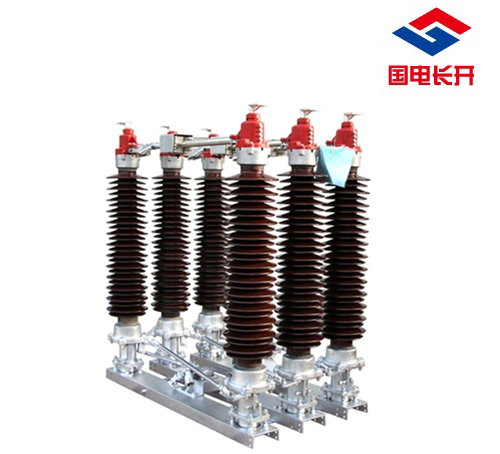
Gw4 isolation switch debugging steps
Hits:395Timer:2019-09-04
Step of three - phase coupling of GW4 isolator
1. Work preparation, safety helmet, safety belt, tools, and division of labor
2. Check the equipment status and pay attention to the position of limit screw
3. First adjust the three-phase crossover connecting rod, so that the knife can be closed at the correct same time position (the contact is just closed at the line of arc R).
4. Place the phase conductive arm of the mechanism in the half-split and half-close state, connect the main crank arm and main tie rod, put the tooth plate in the appropriate position, tighten the screws at both ends, and roughly adjust the main tie rod
5. Manually push the mechanism phase to the joint position, and the mechanism is shaken to the joint position to evenly tighten the vertical connecting rod holding clip
6. The manual mechanism should be divided into one time to observe the total stroke. If it is not suitable, first adjust the tooth plate to make the total stroke fit in place. Through the adjustment of the main tie rod, the opening and closing position is correct. At this time, the phase adjustment of the mechanism is completed.
7. Shake the mechanism to the same position, as long as confirm that it can fit in. Then swing the mechanism to the closing position, observe the closing state of middle phase and side phase, make clear the adjustment direction and adjustment amount of the horizontal tie rod, and return to the half-break and half-break position for adjustment, until the opening and closing position is qualified.
8. Finally, divide the institution into one piece, and check the data of sorting, synchronizing and compounding. After confirming the debugging, tighten all positioning nuts.
9. Disassemble and install three screws in each phase of the disassembly of the ground knife rod.
10. Organize the site and fill in the records.


